
What Is Pump Technology and How Does It Work?
Pump technology turns electrical, engine, or other input energy into moving fluid. Inside a centrifugal pump, a rotating impeller accelerates liquid outward; the casing then helps convert that motion into pressure. In a small building, this may mean water moving through a heating loop. In a factory, it can mean thousands of gallons circulating through pipes, valves, and filters.
The scale matters. The U.S. Department of Energy’s Improving Pumping System Performance sourcebook reports that pumping systems account for nearly 20% of global electricity demand, and 25–50% of electricity use in some industrial operations. Those figures describe systems, not pumps in isolation. Pipe diameter, control settings, fluid properties, and maintenance all affect energy use. A pump can be efficient on a test bench and still waste power when poorly matched to its real workload.
That system-level perspective is central to the published work of pump engineer Dr. Lev Nelik, whose books and technical writing address pump selection, operation, and troubleshooting. A useful paraphrase of his engineering approach is this: assess the pump together with the system it serves, rather than relying on nameplate ratings alone. The distinction is practical. A throttled valve, a clogged strainer, or an oversized motor can quietly raise operating costs. Small details matter.
And efficiency is not the whole story. Engineers also consider reliability, fluid compatibility, pressure requirements, and maintenance access. Understanding these basics makes pump technology easier to evaluate—and helps explain why the right pump is not always the biggest one.
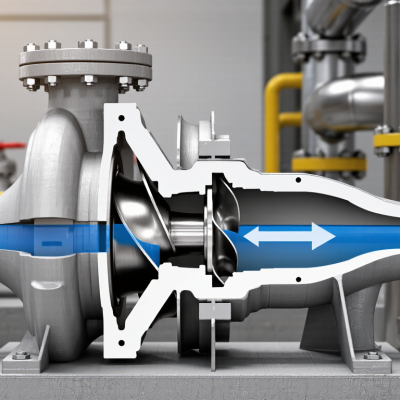
Definition and Purpose of Pump Technology
Pump technology is the engineering of devices that move liquids by adding energy to them. A motor turns an impeller, or drives a moving chamber, creating flow and pressure. That is the job. The right design depends on the liquid, required flow rate, pipe layout, and operating conditions. A pump that moves clean water may not suit a thick or abrasive fluid.
The purpose is practical: deliver water to a tap, circulate coolant through equipment, or move process fluids between tanks. The U.S. Department of Energy’s Improving Pumping System Performance sourcebook estimates that pumping systems use nearly 20% of global electrical energy. That estimate concerns systems, not each pump. System design matters. A correctly sized pump can still waste energy when valves restrict flow or pipes create excessive resistance. In a plant, technicians can check pressure gauges, listen for unusual vibration, and compare measured flow with operating needs. These details help identify poor performance, though measurements and maintenance records are not always complete. That uncertainty deserves attention.
| Topic | How It Works | Purpose or Typical Use | Key Operating Consideration |
|---|---|---|---|
| Pump technology: definition | A pump converts mechanical energy into hydraulic energy to move a liquid, increase its pressure, or help it overcome elevation and flow resistance. | Moves fluids through pipelines, equipment, and treatment or distribution systems. | A pump moves liquid; the connected system determines the flow and pressure at which it operates. |
| Typical pump system | A driver, commonly an electric motor, turns or moves the pump mechanism. The pump transfers energy to the liquid, while pipes, valves, and fittings guide the flow. | Supports fluid transport in buildings, industrial processes, agriculture, and water services. | Correct sizing depends on both the required flow rate and the total system head, including elevation and friction losses. |
| Centrifugal pump | A rotating impeller accelerates liquid outward. The pump casing helps convert some of that velocity into pressure. | Commonly used for water circulation, water supply, irrigation, and many general-purpose liquid-transfer duties. | Performance changes with system conditions. Many designs require priming, and operation should avoid damaging cavitation. |
| Positive-displacement pump | Traps a quantity of liquid and moves it from the inlet to the outlet through repeated mechanical movement. | Useful for metering, viscous liquids, and applications that need controlled flow at varying pressures. | Flow is closely related to operating speed. A relief or bypass arrangement is important because a blocked discharge can create excessive pressure. |
| Diaphragm pump | A flexible diaphragm moves back and forth, drawing liquid into a chamber and then pushing it through check valves. | Used for chemical transfer, dosing, and handling some liquids containing suspended solids. | Material compatibility and the fluid’s solids content must be checked when selecting the diaphragm and valves. |
| Submersible pump | The pump and its motor operate while submerged in the liquid being pumped. | Commonly used for wells, sumps, drainage, and wastewater applications. | Selection should account for liquid depth, temperature, solids, and the pump’s permitted operating conditions. |
| Pump performance | Flow rate describes the volume moved over time; head describes the energy supplied per unit weight of liquid and is commonly expressed as a liquid-column height. | These values help determine whether a pump can meet a system’s delivery requirements. | Actual performance depends on the pump curve and the system curve; the operating point is where they intersect. |
| Efficiency and energy use | Some input energy is lost through friction, turbulence, leakage, and mechanical or electrical losses. | Choosing an appropriate pump and operating point can reduce energy use and wear. | Oversizing, throttling, and running far from the intended operating range can reduce efficiency. |
| Cavitation | When local pressure falls below the liquid’s vapor pressure, vapor bubbles can form and then collapse as pressure rises. | Preventing cavitation helps protect pump performance and components. | Provide adequate inlet pressure, limit suction-side losses, and follow the manufacturer’s net positive suction head requirements. |
Related Posts
-
Why You Need Effective Pump Solutions for Your Business Efficiency
-
2026 Top Pump Solutions for Every Industry Need?
-
How to Choose the Right Pump Technology for Your Needs?
-
2025 How to Pump Direct: Tips for Maximizing Your Output Efficiently
-

2026 Best Pump Solutions for Efficient Water Management?
-
Top 5 Direct Pumps Tips for Global Buyers to Consider?