
A Digital Signal Isolator transfers digital signals between circuit sections while helping limit the effects of electrical noise and voltage differences. These devices appear in industrial controls, medical equipment, energy systems, and communication hardware. Their small packages can conceal important differences. Channel count, isolation rating, data rate, common-mode transient immunity, and operating temperature all influence suitability.
This overview introduces ten manufacturers active in the worldwide market and the capabilities that make their products worth considering. It is a starting point, not a universal ranking: product ranges, regional availability, and technical support can change over time. A datasheet may look convincing, yet a device still needs to match the actual circuit, layout, and working environment. Small details matter. Designers should also check relevant certifications and application notes rather than relying on a headline specification alone. That step is easy to overlook.
The companies covered may include broad semiconductor suppliers as well as firms with more focused isolation portfolios. Comparing them can help engineers identify candidates for closer review, but no manufacturer is automatically the right choice for every project. Even a careful comparison has limits; product revisions and supply conditions can shift. Use the discussion alongside current manufacturer documentation and, where needed, qualified engineering advice.
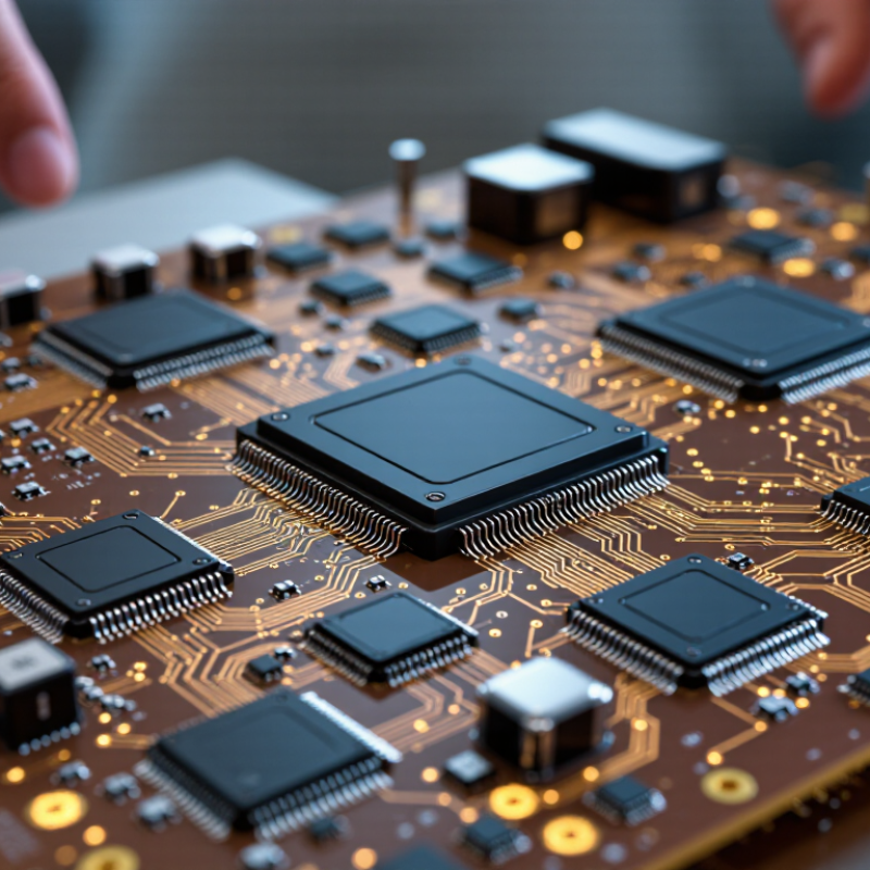
A digital signal isolator transfers logic signals between circuits without a direct conductive connection. It uses capacitive, magnetic, or optical coupling to pass changing digital states across an insulating barrier. No direct path. This separation helps protect sensitive control electronics when two parts of a system sit at different voltages. It can also reduce ground-loop noise, where unwanted current travels through shared ground connections. In a motor controller, for example, an isolator may carry a switching command from a low-voltage processor to a power stage exposed to electrical noise.
The barrier does not make every circuit automatically safe. Its isolation rating, creepage distance, and clearance must suit the operating environment and the board layout. Signal speed matters, too. Data rate, propagation delay, and common-mode transient immunity can affect whether pulses arrive reliably during fast voltage changes. A specification sheet may look reassuring, yet poor PCB spacing can undermine the intended protection. Still, isolation is not magic. Designers should check power requirements and signal timing in the actual circuit, not only on paper. A small timing mismatch can matter in a tightly synchronized system. These details are easy to overlook, especially when replacing a simpler, non-isolated connection.
A digital signal isolator transfers logic across a safety barrier without a direct conductive path. On one side, an input circuit converts a changing voltage into brief pulses. Those pulses cross a tiny gap through capacitive or magnetic coupling. A receiver on the other side reconstructs the original high and low states. The signal crosses; the electrical connection does not. IEC 60747-17:2020 sets requirements for capacitive and magnetic couplers, including insulation and transient-voltage tests. These tests matter because a barrier must withstand more than ordinary operating voltage.
Consider a motor controller beside a noisy inverter. Fast voltage spikes can couple into nearby traces, so designers check isolation rating, creepage distance, data rate, and common-mode transient immunity together. A high data rate alone proves little. The isolation rating is not a promise of safe operation under every condition; board layout, temperature, and contamination also matter. Noise still travels. Industry reports often track market growth, but they cannot replace device-level test data or the system’s actual fault conditions. One uncomfortable detail: a clean lab result may not capture a crowded, warm enclosure with long cables. Engineers should review test conditions, not just headline specifications.
Digital signal isolators transfer logic signals across an insulation barrier using capacitive or magnetic coupling, rather than a direct electrical connection. The input signal is encoded and coupled across the barrier, then reconstructed at the output. This table provides an anonymized, non-ranked overview of common product segments and representative specifications found across commercially available devices. Ranges are indicative, vary by part, and are not attributed to any specific manufacturer.
| No. | Anonymized Market Profile | Typical Isolation Method | Common Channel Configurations | Representative Maximum Data Rate | Typical Isolation Rating* | Common Application |
|---|---|---|---|---|---|---|
| 1 | General-purpose, single-channel segment | Capacitive or magnetic coupling | 1 channel | Up to approximately 100 Mbps | Commonly 2.5–5.7 kVrms withstand, depending on device | Isolated GPIO and control signals |
| 2 | Low-speed, multi-channel segment | Capacitive or magnetic coupling | 2–4 channels | Typically up to 25 Mbps | Part-dependent; commonly in the 2.5–5.7 kVrms range | Status, enable, and control lines |
| 3 | High-speed, two-channel segment | Usually capacitive or magnetic coupling | 2 channels | Approximately 25–150 Mbps for available device families | Varies by package and certification | Fast SPI and serial data links |
| 4 | Mixed-direction, four-channel segment | Capacitive or magnetic coupling | 4 channels, with multiple direction options | Up to approximately 100 Mbps, device-dependent | Commonly 2.5–5.7 kVrms withstand, depending on device | Isolated data and control buses |
| 5 | High-speed, multi-channel segment | Capacitive or magnetic coupling | 2–4 channels | Up to approximately 150 Mbps in selected devices | Part-specific; check the applicable safety certification | High-speed SPI and converter interfaces |
| 6 | High-channel-count segment | Capacitive or magnetic coupling | Up to 6 channels in some device families | Typically varies from low-speed to tens of Mbps | Varies with device and package | Multi-line industrial and instrumentation interfaces |
| 7 | SPI-oriented segment | Capacitive or magnetic coupling | Multiple forward and reverse channels | Commonly tens of Mbps; faster options are available | Device- and certification-dependent | Isolating clock, data, and chip-select signals |
| 8 | I²C-compatible segment | Capacitive or magnetic coupling with bidirectional signaling support | Typically two bidirectional lines | Up to 1 Mbps for devices supporting Fast-mode Plus | Varies by device; confirm the specified working voltage | Isolated I²C communication |
| 9 | Gate-driver signal-interface segment | Typically capacitive or magnetic coupling | One or more control channels | Application- and device-dependent; commonly in the Mbps range | Select according to the gate-drive system's isolation requirements | Isolated PWM and switch-control signals |
| 10 | Industrial serial-interface segment | Capacitive or magnetic coupling | Varies with transmit/receive signal requirements | From low-speed control rates to tens of Mbps | Part- and system-dependent | Logic-side isolation for industrial serial links |
Selection note: Isolation withstand voltage is not the same as continuous working voltage. Verify working voltage, creepage and clearance, surge and transient ratings, common-mode transient immunity (CMTI), propagation delay, temperature range, and relevant safety approvals in the specific device datasheet.
*Isolation figures are broad market examples, not guaranteed specifications for every device or profile. Actual ratings depend on package, test standard, and certification.
Digital signal isolators protect control electronics while passing logic signals across an electrical barrier. Selection starts with the actual system conditions, not a headline isolation number. Compare working voltage, transient withstand, creepage and clearance, and the applicable safety test conditions. Capacitive and magnetic designs can both work well, but their noise behavior and integration needs may differ.
Check common-mode transient immunity (CMTI), propagation delay, channel-to-channel skew, and maximum data rate against the interface and switching environment. A fast isolator is not automatically the best one. Long traces, noisy inverters, and uneven timing can expose weaknesses that a bench test with a clean signal source misses. Small details matter. Also verify operation across the full temperature range and supply-voltage limits; power consumption can affect compact, densely packed boards.
When comparing manufacturers, review complete datasheets, test methods, package options, and product-life information. Ask how isolation performance is characterized, rather than relying on a single marketing figure. A tidy datasheet is not proof of performance in your layout. I would still test the chosen part on the intended board, including during switching transients. No selection is perfect: extra margin costs space or power, and the right trade-off depends on the equipment and its operating conditions.
A worldwide comparison of the top 10 digital signal isolator manufacturers should look beyond headline isolation ratings. Strong suppliers provide clear data on working voltage, transient immunity, propagation delay, and operating temperature. These details help engineers match an isolator to motor drives, industrial controls, or communications equipment. That matters.
Check how each manufacturer supports its specifications. Reliable datasheets explain test conditions, package options, and recommended circuit layouts. Evaluation boards and application notes can also reveal practical design concerns, such as noisy switching edges or tight board spacing. A part that looks suitable on paper may behave differently in a compact layout.
Manufacturers in different regions may specialize in different combinations of data rate, channel count, and package size. Compare equivalent test conditions rather than ranking products by one impressive number. Not always. Also review long-term product availability and the quality of technical support; a fast response to a design question can prevent weeks of rework. Certification claims deserve careful reading, since the relevant approval depends on the end application. I would not treat any top-ten list as permanent: product revisions, supply conditions, and real-world testing can change the picture.
Digital signal isolator manufacturers differ in more than data-sheet ratings. A useful profile examines isolation voltage, channel configuration, propagation delay, and power consumption. These details affect whether a device suits a compact sensor board or a fast industrial control link. Some manufacturers focus on broad product ranges; others prioritize low-power designs or precise timing. Compare published test conditions carefully, since ratings measured under different temperatures or loads may not be directly comparable. The numbers can mislead.
Comparative strengths also depend on engineering support and documentation. Clear timing diagrams, layout guidance, and isolation-barrier specifications help teams review a design before building prototypes. Check package options and operating-temperature ranges against the actual equipment environment. A strong catalog is useful, but it does not guarantee a smooth design-in. Support quality can vary, and public product information may not show every limitation. That deserves a closer look.
Tips: Shortlist devices by application, then compare matching test conditions. Review PCB spacing guidance and transient immunity data. Ask for clarification when specifications leave practical questions unanswered.
